Efficient DC-DC voltage converter through dynamic control of coil inductance
Abstract
This technology increases the efficiency of DC-DC converters by maintaining the maximum possible inductance value (MET) under all operating conditions. The technology is particularly suitable for applications where the inductance values need to be controlled or set.
Background
DC voltage converters (DC-DC converters) enable the conversion of a first DC voltage present at the input of the DC-DC converter into a second DC voltage present at the output. They are, for example, used in battery chargers.
Problem
An important component of many DC-DC converters is the inductor which temporarily stores the energy transferred between the input and output. These coils usually have an inductance that depends on the average value of the current carried by its coil. The inductance value influences the line losses in the coil, so that depending on the operating point of the DC-DC converter, power losses of different magnitudes occur.
Solution
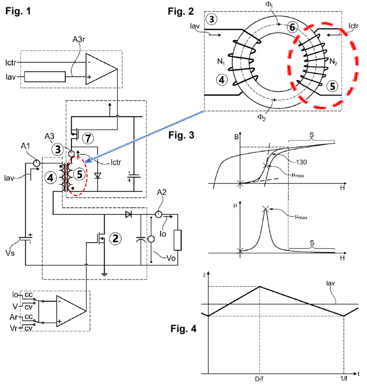
The task of this invention is to increase the efficiency of the DC voltage converter. In the method according to the invention, the average value of the main winding current in the main winding of the coil is set via the pulse duty factor of the circuit-breaker. The setting is made specifically in such a way that the permeability of the coil core (inductance of the coil) assumes its maximum value. The invention relates to a method for operating a DC voltage converter (Fig. 1) comprising a circuit breaker (2) and a coil (3) with a coil core (Fig.2), a main winding (4) arranged on the coil core (6) and a control winding (5) arranged on the coil core, the main winding, carrying a main winding current (I), the average value of which is adjusted via a pulse duty cycle factor (D) of the circuit-breaker (2) so that either a constant output current (lo) or a constant output voltage (Vo) of the DC/DC converter is obtained, and the control winding carries a control current (Ictr) which is set (with circuit-breaker 7) based on the average value (lav) of the main winding current. This way, the efficiency of the DC-DC converter can be increased under any operating condition of the DC-DC converter, i.e. for any output voltage or current, regardless of the geometry of the coil.
Fig. 4 shows the flow of the main winding current of the DC-DC converter depicted in Fig. 1 and Fig. 3 shows a typical development of magnetic flux density and permeability in a coil core.
Advantages
- Maximum efficiency (reduced losses) under all operating conditions (variable input voltage, variable switching frequency) by maintaining the maximum possible inductance value (Maximum Energy Transfer - MET)
- Suitable for applications where the inductance values must be controlled or adjusted (Dynamic Inductor Control - DIC)
Application
Increased efficiency of DC-DC converters, especially in cases where the inductance value is regulated / set.

