Exhaust tract for combustion engines – turbocharger
Abstract
The novel MEDUSA technology for turbocharging combustion engines fits the current trend to downsize engines perfectly. The optimal inflow into the turbine, particularly at low speeds of revolution, makes the engine very responsive, with maximum torque developing in the lower range of rotatory speed. Additionally the exhaust tract that forms part of the invention is extremely robust, in particular at high combustion temperatures. Thus the technology is particularly suited for use in small gasoline engines: the efficiency is greater than for wastegate turbochargers; however, unlike the Variable Turbine Geometry (VTG) turbocharger, this charger does not require adjustable guide vanes.
Background
Turbocharged engines have significant advantages over aspirating engines with a comparable cylinder capacity. The novel MEDUSA (Multiple exhaust duct with source adjustment) technology increases the efficiency of Diesel as well as gasoline engines. As a cost-saving alternative to conventional processes it is of great interest to automobile manufacturers.
Problem
Established processes for the gas flow onto the turbine wheel of a turbocharger all collect exhaust gases from each cylinder in a manifold which subsequently flow onto the rotor via a volute housing. Current approaches include the joining of certain exhaust channels to allow the application of the impulse energy from separate channels onto the turbine wheel (Twin-Scroll-Turbine). All the regulatory functions (such as VTG and waste gate) to control the flow onto the rotor are built into the body of the turbocharger because the flow is uniformly distributed over the periphery of the rotor wheel.
Solution
In the present invention the exhaust gas from each cylinder is completely separated with regard to the exhaust gas guidance and application onto the turbine wheel. Thus the partial application of gases from each single cylinder onto the rotor becomes possible.
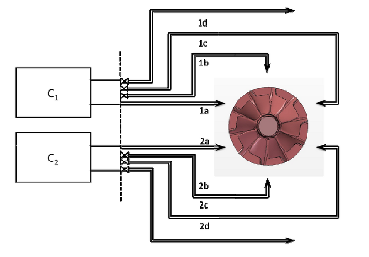
Several channels belong to each cylinder as will now be briefly explained by an example, namely a two cylinder engine. Six inflow channels are distributed around the circumference of the rotor wheel for regulation, three for each of the two cylinders (C1 and C2). These channels are controlled separately according to the exhaust volume flow, whereby each channel applies its exhaust gas to a defined segment of the rotor. A further channel for each cylinder can serve as a bypass (1d, 2d) (see Figure 1).
Advantages
- Optimal flow application onto the turbine, particularly at low rotational speeds
- Fast response characteristics
- Absence of turbo lag
- Very durable, particularly at high combustion temperatures
- Simpler and less expensive to manufacture than VNT and VGT
- Turbocharging for gasoline engines
Application
Turbocharging of Diesel as well as gasoline engines.


